


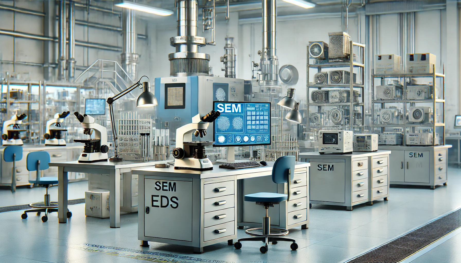
We are happy to announce that Vibra Finish Ltd is now certified IATF 16949:2016. Certificate of Registration: This certifies that the Quality Management System of Vibra Finish Limited, 5329 Maingate Drive, Mississauga, Ontario, L4W 1G6, Canada has been assessed by NSF-ISR and found to be in conformance to the following standard(s): IATF 16949:2016. Scope of Registration: Provision of Surface Finishing Services.
At Vibra Finish Ltd., we take pride in offering high-quality surface finishing solutions, and glass bead blasting is one of the most effective techniques for achieving smooth, clean, and visually appealing surfaces. This guide will provide an in-depth look at glass bead blasting, from its process to its many applications, benefits, and best practices.
What is Glass Bead Blasting?
Definition and Overview
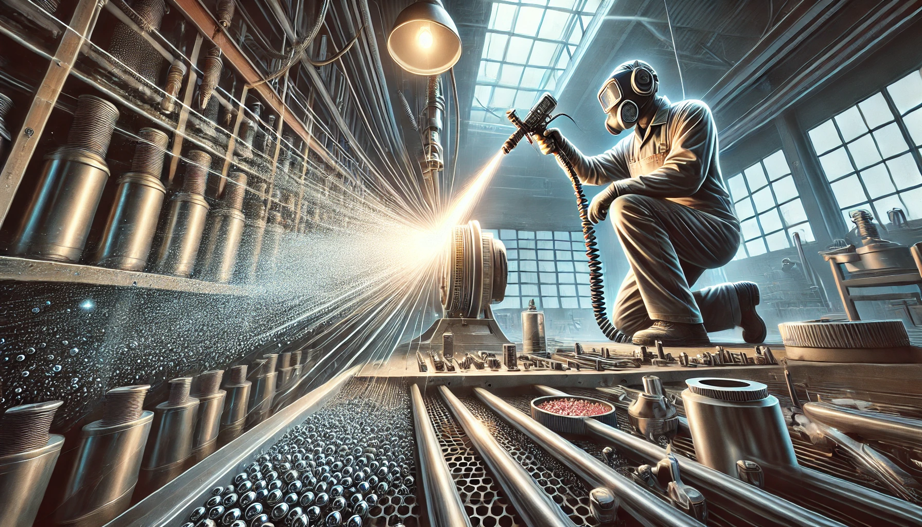
Glass bead blasting is a non-abrasive surface finishing process where spherical glass beads are shot at high pressure onto a surface. The technique is commonly used to clean, polish, and prepare surfaces without damaging the material underneath. Unlike other abrasive methods, glass bead blasting leaves behind a smooth, uniform finish, making it ideal for industries where aesthetics and surface integrity are key.
This method is widely used across industries such as automotive, aerospace, and general manufacturing, where it plays a crucial role in removing contaminants like rust, old paint, and debris, while ensuring the base material remains undamaged.
History and Evolution of Glass Bead Blasting
Glass bead blasting has come a long way since its introduction. Early methods of sandblasting were highly abrasive, which often led to material damage. However, the development of glass bead media offered a less aggressive yet equally effective solution. Over time, advancements in equipment, such as modern blasting cabinets and nozzles, have made glass blasting more precise and efficient, enabling it to be used in more delicate and high-precision industries like aerospace and medical manufacturing.
How Glass Bead Blasting Works
The Blasting Process in Detail
The glass bead blasting process involves several key steps:
- The surface to be treated is cleaned and prepped.
- Glass beads for blasting are loaded into a blasting machine.
- Compressed air propels the beads through a nozzle, directed at the target surface.
- The beads impact the surface, gently removing impurities without altering the material’s dimensions.
Key considerations during this process include choosing the right bead size, air pressure, and maintaining a consistent blasting distance to ensure an even finish.
Equipment and Tools for Glass Bead Blasting
Successful glass bead blasting requires specialized equipment, including:
- Blasting cabinets to contain the media.
- Nozzles of varying sizes for different applications.
- Air compressors to generate the high pressure needed for blasting.
Maintaining equipment is essential for achieving the best results, as worn nozzles or inconsistent air pressure can affect the quality of the finish. Choosing the right tools and regularly servicing them ensures maximum efficiency and performance.
Benefits of Glass Bead Blasting
Surface Finish and Aesthetic Improvements
Glass bead blasting is highly valued for its ability to create smooth, satin, or matte finishes. This is particularly important for applications where appearance and texture matter, such as automotive parts or decorative metals. It not only improves the look of the material but also enhances its ability to bond with coatings, paints, or adhesives.
Non-Abrasive and Environmentally Friendly Solution
One of the primary advantages of glass bead blasting is that it’s a non-abrasive technique, making it safe for surfaces like aluminum and stainless steel, where preserving the material’s integrity is essential. Additionally, glass bead media is environmentally friendly. The beads are made from recycled glass and can be reused multiple times, making them a sustainable option compared to other blasting materials.
Common Applications of Glass Bead Blasting
Automotive Industry
In the automotive world, bead blasting is commonly used for restoring vintage car parts, cleaning engine components, and preparing metal surfaces for painting or powder coating. The process ensures a smooth, rust-free surface without damaging the metal, making it ideal for sensitive automotive restoration projects.
Aerospace Industry
In the aerospace industry, glass bead blasting is used to clean and prepare parts, ensuring that components are free from debris and ready for assembly or coating. This technique is valued for its precision and non-damaging nature, which is critical in aerospace applications where material integrity is paramount.
General Manufacturing and Maintenance
From metal fabrication to machinery maintenance, glass bead blasting is widely used to clean, deburr, and prepare surfaces for further processing. The technique is effective for removing contaminants like scale and rust while preserving the material’s surface properties.
Glass Bead Blasting vs. Other Blasting Methods
Glass Bead Blasting vs. Sandblasting
Compared to traditional sandblasting, glass bead blasting is less aggressive, offering a gentler option for delicate surfaces. Sandblasting can wear away material over time, making it unsuitable for projects where maintaining surface integrity is important. Glass blasting is often preferred for jobs requiring both cleaning and preservation.
Glass Bead Blasting Media: Choosing the Right Type
How to Choose the Best Glass Beads for Your Project
Selecting the right type of glass bead media depends on the application. Factors like bead size, hardness, and the desired finish all play a role in choosing the appropriate media. Larger beads provide a more aggressive finish, while smaller beads result in a smoother surface.
Pros and Cons of Glass Bead Blasting
Key Benefits
- Non-abrasive: Preserves surface integrity.
- Reusable: Cost-efficient and eco-friendly.
Drawbacks and Limitations
While glass beading is effective, it may not be the best option for every project. For example, it’s not as effective at removing thick coatings or heavily rusted materials as more abrasive media.
Safety Considerations in Glass Bead Blasting
Protective Gear and Safety Procedures
Operators should always use appropriate protective gear, such as gloves, masks, and eye protection, to prevent injury during the glass blasting process. Proper ventilation is also necessary to avoid inhalation of dust or particles.
Environmental and Health Impacts
Glass bead blasting is relatively safe and eco-friendly, but proper disposal of spent media is important to minimize environmental impacts. Using recycled beads and ensuring minimal dust emission are key steps toward an eco-conscious blasting operation.
Conclusion
Glass bead blasting offers a versatile, safe, and eco-friendly solution for surface preparation, cleaning, and polishing across a wide range of industries. Its ability to deliver smooth finishes without damaging materials makes it the go-to option for many precision applications.
Frequently Asked Questions
Can Glass Bead Blasting Be Used on All Metals?
Yes, glass bead blasting is suitable for most metals, including aluminum, steel, and stainless steel.
What’s the Difference Between Glass Bead Blasting and Soda Blasting?
Glass bead blasting is more versatile and effective for a wider range of applications, while soda blasting is gentler, often used for softer surfaces.
Can Glass Bead Blasting Remove Rust and Paint?
Yes, glass bead blasting effectively removes rust, paint and mill scale without damaging the base material. For more information on glass bead blasting services, contact Vibra Finish Ltd. today!
Kumar Balan explores the efficacy of vibratory peening, its financial viability and its potential market reach. His article will cover all these aspects courtesy of data provided by Vibra Finish.
In the winter 2018 issue of The Shot Peener, we discussed two non-conventional peening techniques; one of which was Vibratory Peening. In addition to the superior surface finish, we learnt that the layer of compression was deeper with vibratory peening when compared to conventional shot peening. The process itself was significantly different from conventional peening in terms of media life, dust generation and utility costs. We concluded that this technique of generating residual compressive stress was worth further exploration. The results are discussed here.
Vibra Finish, a company based in Mississauga, Ontario (Canada) has conducted multiple studies to validate the established facts and clearly define limitations of this peening process. They have attempted to identify components, both industrial and domestic, that demand and could benefit from a combination of fatigue resistance and superior surface finish, both in a single step process.
When reviewing a new process, especially one that simulates an established technique albeit with marked improvements, skepticism is common. Such doubts include the technical efficacy of the process, financial viability and its potential market reach. Our discussion will cover all these aspects courtesy of data provided by Vibra Finish. Given that Vibra Finish operates conventional shot peening machines as well, our discussion is enriched by the comparison of both techniques under identical process variables.
Background
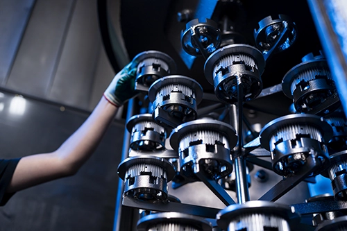
Vibratory finishing is a primary process in its own right and sometimes it is a supplementary process used to polish a shot-peened surface. As a secondary operation, it can eliminate surface roughness created during peening. Surface roughness, greater than a certain application dependent value, can have a detrimental effect on the fatigue life of the component. As we know, most specifications limit material removal in post-peening finishing to 10% of the ‘A” intensity value. Vibratory finishing could be controlled to stay well within this tolerance. Vibratory finishing is also used for deburring, burnishing, descaling and is ideal for finishing parts prior to painting, plating, heat treating, anodizing or simply to achieve an excellent final finish.
Vibratory finishing is categorized as a “mass-finishing” process, and when designed properly, will result in a batch of parts that is treated with uniformity and consistency. The process is not reliant on operator skill unlike certain other techniques such as buffing, filing, belting, etc. Instead, a batch of parts are loaded in bulk into a tub or continuously fed to a vibratory machine for inline operation. The tub is filled with finishing media and suitable compound(s) that when combined act as thousands of small filing surfaces scrubbing the parts. The compound assists the cleaning/finishing action of the media (usually made from ceramic). The choice of compound will depend on the material to be treated, the desired surface finish, and the individual application and process requirements. Additives in the compound could serve other purposes such as alkaline cleaning, acidic burnishing, washing and rust inhibition.
Just like any other process, vibratory finishing has controllable variables that alter the finish quality. Two of the main factors include the amplitude and frequency of vibration. Given the advantages of this process, it is a natural progression that vibratory finishing be extended in its application range to provide a peened and finished product in a single step.
Past Research
In 2016-17, Dr. Hongyan Miao and Prof. Martin Levesque from Polytechnique Montreal studied the fatigue life improvements of a certain alloy type using conventional peening and shot peening. The results from this test were encouraging enough to carry out further testing. The details of their testing are as follows:
- Conventional shot peening was carried out in an Automated air type machine with a V2″ diameter nozzle propelling Z425 ceramic bead on the component. The target intensity was 8A, achieved at an air pressure of 20 PSI and media flow of 10 lb./minute. The part was fixtured on a rotary table.
- Vibratory peening (this term is used to signify the sole purpose of this operation-peening) was performed in a batch-type tub filled with AISI Type 1018 Carbon Steel balls with diameters 1/8″, 3/16″ and Vi”, adding up to almost a ton in weight. The target intensity remained unchanged from 8A as in the conventional peening machine.
- It is interesting to note the mix of media sizes in this process as compared to conventional shot peening where the reliance is on consistent media size, to the extent of using classifier screens to maintain the same in the machine. Due to proprietary nature of this process, further elaborations on the use of multiple media sizes is not readily available. A reasonable explanation would be to consider the mechanism of media movement in a batch-type tub, and the interaction of one size with another much like on a pool table. This is compared to conventional peening where a steady stream of media impacts the target.
- Both media types (ceramic and carbon steel balls) were of comparable hardness in the range of 60 HRC.
- In contrast to conventional shot peening where the part spinning on the table was targeted by the abrasive, the part in the vibratory tub was positioned 10″ below the ball bed surface with constant contact of the carbon steel balls.
The team plotted saturation curves using data sets obtained from both peening techniques and, with their distinct process parameters, they arrived at an intensity of 8.3A and 8.6A with shot peening and vibratory peening respectively. Residual stress measurements carried out on the test parts using X-ray diffraction displayed some interesting results. Shot peening produced a larger surface and maximum compressive residual stress (-212 MPa and -297 MPA respectively), as compared to -148 MPa and -225 MPa produced with vibratory peening. However, the difference was in the depth of compression. Vibratory peening produced -50 MPa at 520 micron below the surface whereas with shot peening, the same magnitude of residual stress, -50 MPa, went only 340 micron deep into the surface. In practical terms, if we are able to alter the process parameters in vibratory peening so that it generates the same magnitude of compressive stress as shot peening, we can expect this stress to stretch over a greater depth than with shot peening.
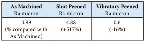
The surface roughness results were as expected. The study compared the surface roughness of the sample part as machined, shot peened and after vibratory peening. Roughness was tested on three samples, on three individual locations and the trend was the same in all cases. One such set of results is documented below for brevity.
Fatigue tests performed as part of this study generated similar average fatigue lives for both processes. However, they did find that the values from shot peening had significantly less standard deviation (minimal variation). The study concluded that rather than comparing similar Almen intensity values, future studies should compare the fatigue life measures for similar residual stress profiles, at different levels of roughness. Ultimately, the measure of all such processes is based on the extent to which fatigue life has been impacted, preferably in the positive direction.
Commercial Components and Vibratory Peening
Encouraged by the results of the previous tests, Vibra Finish continued with comparative tests on more conventional components – a turbine blade and an automotive transmission gear. The tests were to study the following:
- Compare the effects of shot peening and vibratory peening on (a) open and (b) relatively closed geometries in order to learn the limitations presented by certain part types to this process.
- Surface roughness
- Residual stress and nature of curves (relieving of compressive stress as measured into the depth of the part)
The conventional shot peening process was carried out in an automated airblast machine under the following process parameters: Target intensity: 10 to 12A and 100% coverage. This was achieved using SI 10 regular hardness steel shot propelled at 30 PSI by a Vi” diameter nozzle at a stand-off distance of 8″ for a time cycle of 30 seconds.
Vibratory peening was carried out using single size, 3 mm diameter steel balls, in a batch type tub for a total cycle time of 10 minutes. Two sets of data, one for surface roughness and the other for residual stress (using X-Ray Diffraction) were analyzed.
Surface Roughness Data:
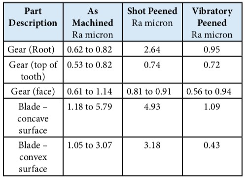
The surface finish results show an interesting trend in a relatively closed geometry component (gear) when compared with the blade with wide, open surfaces. The root section of the gear, which is the area of maximum stress concentration, is the most important region for measurement. In this region, the shot peened component exhibited a much rougher surface finish when compared to an identical vibra-peened component. All other regions of the gear such as the drive face, coast face and tip showed comparable surface roughness values in both processes. Geometry of the gear tooth, media access and media size could all be factors that might have contributed to the final roughness value in vibratory peening.
Though S110 was ideally suited to peen the smallest radius of the gear tooth without causing coverage issues, the surface roughness ended up much higher than with vibratory peening. However, we have to consider the fact that in order to achieve the same intensity (8 to 12A), the S-110 would’ve had to penetrate deeper than the 3 mm balls in vibratory peening, resulting in a rough surface profile.
A study of the residual stress profile provided further insight into the characteristics of both processes to induce compression in the parts.
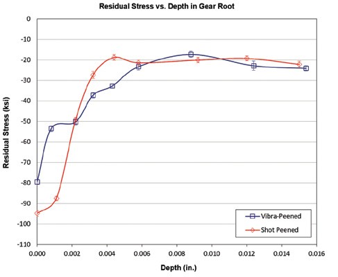
Gear
The residual stress curve for this component is different from the classic “J” hook curve that was expected before the results were obtained. Also, this is a carburized component that may not necessarily show high values of residual stress when shot peened with SI 10 size media to a relatively lower intensity range (8 to 12 A). Though the residual stress at the surface of the shot peened sample is greater than that achieved with vibratory peening, the dissipation (or loss) of residual stress towards the depth of the material is much more controlled with the vibratory peened sample. Vibratory peening did record a seemingly anomalous reading when measured at 0.0008″ depth, registering a steep 33% drop from -79 ksi to -53 ksi before continuing with a controlled and gradual decline at deeper levels into the sample.
An obvious question that remains to be evaluated is whether the surface finish (roughness) was the cause of this steep drop in residual stress in the shot peened sample, especially considering the smoother surface after vibratory peening. The gear being carburized might have also led to the relatively lower magnitude of residual stress using both types of peening techniques.
Blade
A blade from a turbine wheel was chosen for its open geometry. As it turned out, the resultant residual stress followed the all-familiar J-hook pattern. Surprisingly, the compressive stress generated at the surface was greater with vibratory peening when compared to the shot peened sample. Once again, the open geometry of the part and material properties (softer than the gear) likely caused this result. An interesting observation is to be made at 0.0021″ depth where both processes register the maximum compression. Assuming the shot-peened part had developed a rough profile after peening, if one were to polish it by 10% of the ‘A” intensity value, i.e., 0.0011″, we will end up with a higher residual stress value (about -140 ksi) at the surface of the shot peened part. At this depth, the vibra-peened part will have a residual stress of-113 ksi without the need to be polished.
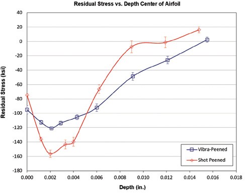
- The drop in residual stress when going deeper into the component was drastic with the shot-peened part and followed a gradual decline with the vibra-peened component. This is a positive attribute of the latter process.
- In both cases, it appears that the geometry of the part played a big role in generating increased magnitude of residual stress.
Conclusions and Future Steps
Vibratory peening certainly shows a lot of promise in terms of combining the two essential features in surface finish— smooth profile and compressive stress—in a single step. Moreover, in both examples, it has shown a gradual and smooth dissipation of this stress as one travels deeper into the material, demonstrating the controllability of the process. The next steps are to study the operating cost of both processes to assess the financial viability of the process. Vibratory peening does not possess the same consumable pattern that we are all familiar in conventional shot peening. This is also true in terms of capital costs involved in procuring a conventional shot peening machine.
Vibratory peening has yet not been governed by a specification. This might be the next step to increase the adoption of this process in known sectors. Meanwhile, a whole range of consumer parts could greatly benefit from this combined process.
About Vibra Finish
Vibra Finish, located in Mississauga, Ontario, Canada, offers a full range of vibratory finishing services and equipment. Their services include deburring, burnishing, descaling, vibrapeening, polishing, rust removal, cleaning, drying, corrosion protection, and peening services. Visit: vibra.com for more information.
Source: The Shot Peener